- Thread starter
- #141
Navigation
Install the app
How to install the app on iOS
Follow along with the video below to see how to install our site as a web app on your home screen.
Note: This feature may not be available in some browsers.
More options
You are using an out of date browser. It may not display this or other websites correctly.
You should upgrade or use an alternative browser.
You should upgrade or use an alternative browser.
Done : Bf109G-6 Yellow 9 of JG54 Gruppe Build
- Thread starter lesofprimus
- Start date
Ad: This forum contains affiliate links to products on Amazon and eBay. More information in Terms and rules
More options
Who Replied?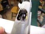
- Thread starter
- #143
lesofprimus
Brigadier General
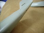
Yep... it is not the nicest fitting.Some putty seems to be needed.
As far as these bulges are concerned.I haven't seen a pic with a view from the another side of the crate.It was discussed somewhere in the forum.But I don't remember if it was about the particular Bf109G.Judging by the late fin and rudder it is possible the starboard bulge was like the top one in your pic.
As far as these bulges are concerned.I haven't seen a pic with a view from the another side of the crate.It was discussed somewhere in the forum.But I don't remember if it was about the particular Bf109G.Judging by the late fin and rudder it is possible the starboard bulge was like the top one in your pic.
Lucky13
Forum Mascot
Will see if I can find something....
Lucky13
Forum Mascot
B*ll*cks...! No bl**dy luck! 
109ROAMING
2nd Lieutenant
Cool work Les, Looks good
Airframes
Benevolens Magister
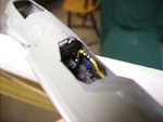
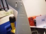
Great work on that awkward tail joint Dan, and the cockpit looks bl**dy good in-place!
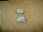
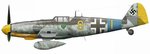
The profile shows the cockpit air-intake, which should mean that the aircraft was unpressurised, but, unless there's a pic of the starboard side, there's no proof. If it WAS pressurised, then the lower bulge, with the extra, smaller bulge at the bottom, would be used. However, if in doubt, I'd fit that one anyway, as it is very possible that they would have been used as the norm, to save in production etc.
The profile shows the cockpit air-intake, which should mean that the aircraft was unpressurised, but, unless there's a pic of the starboard side, there's no proof. If it WAS pressurised, then the lower bulge, with the extra, smaller bulge at the bottom, would be used. However, if in doubt, I'd fit that one anyway, as it is very possible that they would have been used as the norm, to save in production etc.
- Thread starter
- #151
lesofprimus
Brigadier General
Thanks for lookin Jan.... I would say that u have completely confused me now Terry.... Lets see what Wayne has to say bout it.....
Appreciate the comments guys....
Appreciate the comments guys....
- Thread starter
- #153
lesofprimus
Brigadier General
So Im better off using the top bulge in the pic, without the extra bulge???
Airframes
Benevolens Magister
Ah! Now I understand!
Sorry Dan, someone once told me that the small bulge was for covering the compressor for the cockpit pressurisation system. What Wojtek stated about the engine makes more sense, and has started bells ringing. What I meant by using the 'bulged' bulge anyway, was that it's possible some aircraft came of the various assembly lines with this fairing fitted anyway, regardless of which ebgine etc would be fitted.
BUT, in the light of what Wojtek has said, I agree, I'd use the 'plain' cannon-breach bulge.
- Thread starter
- #155
lesofprimus
Brigadier General
Great, thanks for claifying that Terry and Wojtek....
Screaming Eagle
Senior Master Sergeant
Great progress Dan!
According to my info G-6 had been introduced into assembling shortly before G-5. There was a possibility of equipment it wit both DB605A and DB605D.The feature was called "Umrust-Motor".The diference was in an engine cooler radiators.For DB605A it was Fo870 radiator but for DB605D it was Fo987 one.
Waht is more I'm not sure if the G-6s were equipped with the pressurised cockpit at all.The main feature of the kind cockpit mount was a luck of small air intakes on sides below the windscreen.By the way, the pressurised cockpit was made with rubber insultation of the fuselage at the cockpit area from the cross-section between the engine compartment and the cocpit,including the cockpit floor, cockpit sides and the armour plate finishing the cockpit.The new cockpit conopy was made of double glasses sealed up with rubbers with smal boxes of CaCl2 between them to absorb moisture .So it seems that there wasn't any special system of the cockpit pressuration.Simply the cockpit was hermetic only.
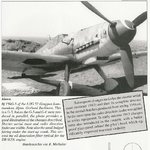
Here is a pic of G-5 with caption I told you above. Source Muschroom Model Magazine Special Bf109G Yellow series vol.1.Note that there is a small air intake below the windscreen side.
Waht is more I'm not sure if the G-6s were equipped with the pressurised cockpit at all.The main feature of the kind cockpit mount was a luck of small air intakes on sides below the windscreen.By the way, the pressurised cockpit was made with rubber insultation of the fuselage at the cockpit area from the cross-section between the engine compartment and the cocpit,including the cockpit floor, cockpit sides and the armour plate finishing the cockpit.The new cockpit conopy was made of double glasses sealed up with rubbers with smal boxes of CaCl2 between them to absorb moisture .So it seems that there wasn't any special system of the cockpit pressuration.Simply the cockpit was hermetic only.
Here is a pic of G-5 with caption I told you above. Source Muschroom Model Magazine Special Bf109G Yellow series vol.1.Note that there is a small air intake below the windscreen side.
Attachments
Two sources I have state that the small "bulge" is for the pressurisation compressor on the G-5.
Quote from Bf109F,G K series by Prein and Rodeike "In general the G-5 resembled the G-6 in all respects except that it had a pressurized cockpit. With the adoption of MG 131 heavy machine guns in place of the earlier MG 17s there was no longer room for the pressurization compressor on the left, upper side of the engine block. It was therefore relocated to the right side of the engine and was responsible for the small tear drop shaped fairing seen beneath the bulge for the MG 131. The compressor inlet scoop was moved from the leftside of the cowling to a position above the compressor fairing. Although totally superfluous for non-pressurized machines, the compressor fairing was retained by many later G-6 and G-14 models, often without the inlet scoop, however."
Now it is still a guess as to whether the 'bulge' was present or not..?? Sorry Dan it still really becomes your call
Users who are viewing this thread
Total: 1 (members: 0, guests: 1)