Eduard 1/48 Bf-110C

Ad: This forum contains affiliate links to products on Amazon and eBay. More information in Terms and rules

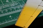
During the course of this exercise, I've found that the decals provided by Eduard for the fuselage Balkenkreuz scale to 900mm whereas Ullmann and Eagle Cals state that these should be 1000mm. Despite this, the Eduard crosses look perfect for the fuselage. Can anyone confirm if 900mm crosses were used on the 110 fuselage?


I just got a set of aftermarket crosses (FINALLY!) and according to the go by - the fuselage crosses for the 110 were 1000 mm, with the upper wings at 1000 mm and the lower wings at 1200 mm. But it's just a go by. If the 900 mm look right why not stick with them?
 
Last edited:
Looking good Andy. I've just measured some 1/48th scale plans, with crosses for different schemes and periods, and checked the proportional grids for Luftwaffe markings orders. It seems 1,000mm is used, but also 900mm. Possibly a period change, sizes relative to adjacent lettering style, or factory/field differences, I'd have to check further to confirm.
 
Thanks everyone for your comments. Dwight, Terry, thanks for commenting on the crosses. I'll probably juts stick with the ones provided with the kit. The difference between 1000 and 900 mm in 1/48 is only a couple of millimeters so not worth the fuss really. I actually tried scaling the vertical length off the photo, knowing the hoizontal would be foreshortened by perspective, and comparing it with the fin but I could get nothing to work out. The picture has a lot of lens distortion I believe, making this difficult.

Last night after some deliberation, I decided to bite the bullet and show the leading edge slats in their open position which is proper for most parked Messerschmitt aircraft and often misrepresented by many model manufacturers. Armed with razor saw and a sharp Xacto knife, I therefore cut out the slats and began filling in the opening on the wings. Pics to come.
 
Work on the slats has been slow but here are some pics.

Pic 1 shows the filled in area behind the cut out slat. This was done using plastic card and the gaps filled with Squadron Putty. To be a true representation, this area should acutally be slightly curved, like an airfoil leading edge but so much of it will be hidden that it's not worth the bother. Not shown are slots cut with an Xacto blade to receive linkages shown in the next pic.

Pic 2 is a close-up of the slat. The trailing edge had to be filled down to a knife-sharp edge to appear real. Two linkages were added with plastic card. These will be inserted in slots cut into the wing surface shown in Pic 1 so the shape had to be adjusted further after this shot was taken so that the slat positioned itself correctly.

Pic 3 Dry fitted slat. The linkages have been inserted into the slots cut in the card in the wing. There's a bit of a warp that I'll need to try and straighten out before gluing. The white bit on the end is a filler piece of plastic card glued on to make up the material lost in sawing.

Pic 4 Same slat from the underside. Before gluing all this in, I'll remove the slat again and give the interior surfaces a coat of 02 (correct for this application I assume)

Thanks for your continued interest. Much more to come.
 

Attachments

  • 100123 Behind Slat.jpg
    100123 Behind Slat.jpg
    83.2 KB · Views: 216
  • 100123 Slat Detail.jpg
    100123 Slat Detail.jpg
    101 KB · Views: 202
  • 100123 Slat Topside.jpg
    100123 Slat Topside.jpg
    83.8 KB · Views: 225
  • 100123 Slat Underside.jpg
    100123 Slat Underside.jpg
    91.4 KB · Views: 200
Razor saw for the two cuts parallel to the airflow and a brand new Xacto blade in the recessed longitudinal lines run back and forth a little at a time until pierced through.
 

Users who are viewing this thread

Back