**** DONE : 1/48th scale N.A. Mustang III, HB837, 541 Sqn, R.A.F., Group Build.

Ad: This forum contains affiliate links to products on Amazon and eBay. More information in Terms and rules

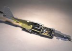
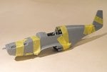
Great shots Antoni! Notice the overspray on the prop blades Terry...nice little 'extra' detail!
 
Yep, noticed that Evan! One of those things which, if included on the model, someone would be bound to say 'Made a mess of that prop, didn't he' !! Also confirmed the (slightly) larger size of the fin flash, incorporating the white stripe, and what appears to be the lack of exhaust shrouds from the manifold - need to have a closer look at this though. Also, presumably due to rather quick conversion and transfer, the fairly clean appearance of the PRU Blue.
With a bit of luck, if I get the Harrier and Lanc finished within the next couple of days, I can finally make a start on this!!
 
White overspray on the prop blades is typical of Mustangs. They didn't remove the spinners when they painted them white.
 
Yep, I'd noticed on some other pics. Hmm - do I don't I include the overspray........?
 
More than a month into this GB, and I haven't even opened the box yet! Hopefully, the stiffness and pain might recede enough to allow me to start soon. The first jobs will be to drill the camera port in the lower, port side fuselage, and construct the actual housing. Then it's time to start on the cockpit, and 'plate over' the Mk1 -type floor with plastic card, to represent the plywood flooring fitted to the MkIII (P51B/C), before adding a bit of extra detail, foil harness straps etc.
With a bit of luck, and an extra dose of painkillers, I should have some pics soon.
 
Well I've made a start, and immediately dropped two rather large b*ll*cks!!
I don't know if it's the distraction of the pain, now thankfully nowhere near as bad, or thinking too far ahead as to which way to best assemble the bits and pieces, this being my first ICM build, even though this kit is almost certainly a 'borrowed' Tamiya kit!
The first mess-up was almost a mini-disaster, as I started to drill the hole for the lower fuselage camera port in the wrong place!
PIC 1. shows the result, with the 'error' at bottom left, and the correct aperture above and to the right, awaiting clean-up. The other, smaller hole is the lifting/jacking point. The camera port will be 'boxed in' beneath the radiator trunking once the fuselage halves are joined, and a lens fitted and glazed after painting the model. The 'mistake' can easily be filled and blended in.
PIC 2. shows the second f*** up, where the shoulder straps of the seat harness are too wide, and the adjusters out of line! These are made from metal foil, so I'll remove them and make and fit another set. Also shown in this pic is the radio rack and radio, deliberately mounted 'back to front', in order to move it aft, to leave space for the second camera, which was mounted immediately behind the pilots bulkhead frame, facing obliquely to port. The camera will be scratch-built from plastic tube and sheet, and fitted next. The other items in this pic are the cockpit side frames, which I discovered needed a bit of trimming in order to align with the cockpit assembly. It's going to be very important to ensure that all internal fittings are aligned accurately, to avoid problems when the fuselage halves are joined, as there are no locating pins on the major parts. Those of you building ICM kits at the moment, or those intending to, make sure you constantly test-fit as you go along - the parts should fit in theory, but in practice it can, and probably will, be different!
One thing which did turn out as planned, more or less, was the 'plywood' flooring, covering the curve of the Mk1 'floor', which was, in fact, the upper section of the wing centre section. This was cut from plastic sheet, glued in place, and suitably painted, and the control column actuating rod to the elevators was shortened accordingly.
PICS 3 and 4 show the instrument panel in place. I did take some pics of this, but got the lighting wrong, as the 'dials' reflected everything and 'washed out' the details! Of course, I'd already fitted the darned thing by the time I came to edit the pics!
The next step is to make and fit the camera, after correcting the seat harness, then do some re-touching, before adding tabs of scrap plastic at strategic points along the edge of one fuselage half, to aid in joining both halves together. Once that's done, it's time for the wings, probably some filling and sanding, then concentrate on the bits and pieces before the first painting stage.
Thanks for your interest, and I should have some more pics soon.
 

Attachments

  • D Day mustang 006.jpg
    D Day mustang 006.jpg
    27.9 KB · Views: 166
  • D Day mustang 011.jpg
    D Day mustang 011.jpg
    43 KB · Views: 168
  • D Day mustang 016.jpg
    D Day mustang 016.jpg
    38.7 KB · Views: 167
  • D Day mustang 019.jpg
    D Day mustang 019.jpg
    34 KB · Views: 167
The offending seat harness straps have been replaced, and the camera body, motor drive and lens etc fashioned from scrap plastic, plastic tubing and stretched sprue, with the front lens element being represented by a blob of Micro Kristal Klear. It's supposed to represent the 5x5 inch format, F.24 camera with the 8 inch lens (U.S. equivalent = K.24) and, whilst not totally accurate in shape, should look good enough under the distortion of the open canopy. The Type 35 camera control unit has been made from scrap plastic, and fitted to the port cockpit wall, above the trim controls. The cockpit is a bit rough in places, as my hands are still a bit stiff, but most of it can only just be seen once closed up, and hardly at all if the canopy was to be left closed, so I'm not to concerned on this occassion!
The cockpit and other internal fittings have been cemented into the fuselage halves, with the oil cooler in the starboard side, the rest in the port, to aid in joining both halves, as there are no locating pins on ICM kits. In order to further ensure an accurate alignment of the fuselage, tabs of scrap plastic have been superglued and cemented at a few points along the edge of one fuselage half.
After everything had set, the fuselage was joined, applying cement in stages, working forward from the tail, and then firmly taped together until set. I'm happy to say that there are no gaps, and everything appears to be square, without any apparent warping or distortion.
PIC 1 shows the camera under construction, with the film magazine and power lead yet to be added, and everything smoothed off and cleaned.
PIC 2. The camera painted and installed on the front of the radio rack. The 'lens' has yet to set clear and, once it has, this, and the lens barrel, will be given a coat of gloss and semi-gloss varnish respectively.
PIC 3. The cockpit and other internal fittings in place. The Type 35 camera control unit can just be seen (the grey 'box'), to the left of the control column.
PIC 4. A general view of the port fuselage half, showing the white plastic tabs glued firmly in place, to aid in alignment when joined.
PIC 5. All cleanly joined, and firmly taped together. So far, it looks like filler will not be needed at all on the fuselage, but I'll find out when the tape is removed!
So, next step is to assemble the wheel wells and main wings, which I'm hoping will go together and mate-up to the fuselage without too much drama. Anyone who has built the Tamiya P51B/C will instantly recognise the main parts of this ICM kit, as they are identical, but have some added detail and extra parts. I believe there was some sort of cooperation betwen the two companies, which probably explains ICM figures in some Tamiya kits.
Thanks again for flying with...oops, sorry,... thanks for looking, and I'll post more soon.
 

Attachments

  • D Day mustang 026.jpg
    D Day mustang 026.jpg
    62.6 KB · Views: 146
  • D Day mustang 037.jpg
    D Day mustang 037.jpg
    32.5 KB · Views: 148
  • D Day mustang 029.jpg
    D Day mustang 029.jpg
    50 KB · Views: 162
  • D Day mustang 043.jpg
    D Day mustang 043.jpg
    28.8 KB · Views: 165
  • D Day mustang 046.jpg
    D Day mustang 046.jpg
    25 KB · Views: 150

Users who are viewing this thread

Back