H.P. Halifax B.MkIII Dedication. (1 Viewer)

Ad: This forum contains affiliate links to products on Amazon and eBay. More information in Terms and rules

With everyone here Terry, this is going to be a magnificent build and a great tutorial for all of us. Really looking forward to watching you turn this into a work of art.
 
Pub? I've forgotten what it looks like!
Don't get yer knickers in a twist - work has started on the Halibag, but I don't think you'd want to see pics of sanding dust!
I'll post some pics of the initial cutting and modifications as soon as there's something to show - which won't be long, honest!
 
He he, I'm looking very forward to seeing it! Can't wait! I built this exact kit when I was about ten... it 'crashed' in my front yard as part of one of my boyhood mock WW2 battles!

Well I shan't pressure you old boy...but I'm looking forward to seeing your treatment of the old girl!
 
Thanks awfully old chap!
And here we go, a rather long post, for which I make no apologies - serves you all right for taking the p*** !
As seems to be the norm with some of my builds, it's destruction before construction, which, in this case, is required in order to have the model in the planned diorama setting.
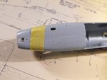
At this stage, only the fuselage is being dealt with, starting with the rivets. From what I remember of this kit from the 1960s, the thousands of rivets were quite heavy, even for the standards of the day, although the shiny black plastic of the time might have exaggerated things, and they were an innovation for the time. I was therefore pleasantly surprised to find that, although still somewhat 'heavy', they are nowhere near as bad as I feared, and a light sanding has reduced them to an acceptable 'ghost' image, which hopefully should look like flush rivets once the model is painted and clear coated - if they show at all.
With that task completed (but with the same to do on the wings yet), work could commence on removing unwanted parts, correcting those alignment faults illustrated earlier, and doing any major cutting, filing or sanding required. The bomb bay and hatches were first on the list, and the pictures will show what was required.
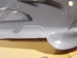
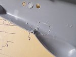
PIC 1. The rear of the bomb bay door hinge lines were extended aft, to immediately in front of the H2S dome, as previously described, by scribing in the hinge line, using the tip from an old pair of dividers, clamped into a pin vice. Note that the vertical line angles towards the front as it curves on to the fuselage sides. The doors are in two sections on each side, with the smaller rear section angled upwards to the rear at the hinge line, following the curve of the fuselage, and these sections were removed first, using a fine blade in a razor saw.
PIC 2. When doing this type of work, always check inside the part, as the vertical and horizontal cuts meet, as stress marks can occur due to the part moving as it becomes loose. It's normally better to make the vertical cut first, to minimise the possibility of the plastic splitting or cracking along the length of the fuselage. Here, a stress mark is clearly visible, albeit small, and this could cause the part being removed to come away leaving a ragged edge, or breaking into unwanted areas. From this point, returning to the outside, the remaining cuts were done slowly and carefully, supporting the now sagging door until the cut is complete, and the part comes free. Do not be tempted to force the part, or snap it off.
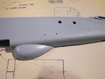
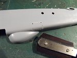
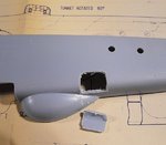
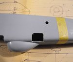
PIC 3. Both sections of bomb doors are now off, and will be discarded. Unlike the Lancaster, the doors of which hinged downwards, one on each side, the Halifax had doors which were horizontally split, and folded together, on each side of the fuselage, and these will have to be scratch-built later, using plastic card.
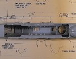
PIC 4. With the doors removed from both fuselage halves, the location points of the internal parts can now be checked, in order to plan the construction of the kit's internal bulkheads and floors, in relation to the scratch-built bomb bay bulkheads and roof. This indicates that the flight engineer's compartment forward bulkhead may double as the forward bomb bay bulkhead on it's bottom section, but the rear bulkhead, as supplied in the kit, will protrude into the bomb bay itself on the lower portion. This will be modified accordingly, and will possibly also provide some structural rigidity to the bomb bay roof when fitted. Test fitting will reveal all !
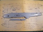
PIC 5. With all the doors removed, and the fuselage halves taped together, this shows the huge void which has to be covered by the scratch-built bomb bay. Everything else inside the fuselage aft of the flight engineer's compartment will not be visible, and so this area will only receive a coat of the appropriate colour paint, to give some 'depth' to any light getting through the two glazed hatches and the dorsal turret, on top of the fuselage.
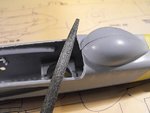
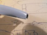
PIC 6. Cleaning-up the sawn edges and correcting any minor irregularities, using a jeweller's file, followed by fine-grit wet n' dry.
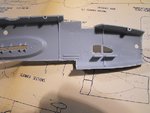
PICS 7 to 12. This is a 'safe' method for cutting out a hatch, or similar aperture, where there is no outer edge to access, as there is on the bomb doors. As previously described, the shape of the entrance hatch needs to be modified, and it is going to be posed open. The hatch door swings upwards and inwards, and may be scratched later, although it can't really be seen inside the fuselage.
First step is to mark the required corner points, and then drill a hole at each point, inside the proposed cut lines.
Next, the shape of the hatch is then lightly scribed into the plastic, which not only provides a cutting guide, but allows a 'key' for the saw blade to grip without slipping. The cuts are then made between each pre-drilled hole, working slowly and carefully, especially on an area as small and compact as this.
As with the bomb doors, the inside face should be checked as the cut lines begin to meet, in case of stress fractures. In this particular case, there is a locating hole 'sleeve' moulded across the full width of the bottom of the fuselage. This could not only cause a stress fracture, but will also be difficult to saw through, with the possibility of trapping, or worse, or snapping, a saw blade, as the plastic is roughly three times as thick as elsewhere.
The simple remedy is to file down the 'sleeve' where it joins the cut line for the hatch. The cutting of the hatch can now proceed, again slow and gentle.
Again, do not be tempted to press the hatch out, or snap it off - just continue gently sawing until it comes free, as here. The rough edges can now be cleaned-up, and filed and sanded to the correct shape, as shown in the final picture in the sequence, where the edges have also been thinned to give a more scale appearance, allowing for the 'look' of internal edge frames and the fuselage floor, the latter to be made and fitted later.
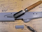
PIC 13. The aperture for the bomb-aimer's rear view blister was made by a series of horizontal saw cuts, on each fuselage half, after taping the halves together and scribing in the shape. The plastic was then pared away, using a scapel, and the aperture filed to the required shape.
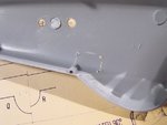
PIC 14. Here we see the aperture during filing, and also, at top, the aperture for the vertical camera. This was done by drilling three holes, in a line, then cutting through to make one, elongated hole, which is in the process of being filed to the correct shape. Also seen here is the escape hatch, scribed using the same tool as earlier. When done, the area will be lightly sanded and polished.
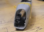
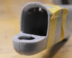
PIC 15. The nose opening has now been filed to the correct profile, and the thick edges thinned down, but leaving sufficient plastic for the transparent nose cone to fit on to. The circular windows have also been thinned around their inner edges, in an attempt to create a better scale appearance.
PIC 16. The mis-aligned tail-turret area has now been corrected, and the turret slipstream deflector re-shaped internally, and thinned down at the edges. Once the fuselage halves are properly joined, further filing will be done, as required, to obtain a level turret platform, and ensure the seams are even.
So, that's most of the fuselage preparation work completed. Next stage is to plan, make and fit the bomb bay components, in conjunction with the kit's few internal fittings, and add some basic internal detail to those areas which can be seen, if only just, through the transparencies.
Thank you all for your interest and obvious enthusiasm for this project, and I hope to continue with the next stage of this build/tutorial later today - if I get some kip!
After the debacle that is the Tornado, I'm trusting that 'The Seven Ps Formula' will work out fine this time around !
 

Attachments

  • Halifax build 025.jpg
    Halifax build 025.jpg
    65.2 KB · Views: 112
  • Halifax build 032.jpg
    Halifax build 032.jpg
    44 KB · Views: 109
  • Halifax build 029.jpg
    Halifax build 029.jpg
    64.6 KB · Views: 115
  • Halifax build 030.jpg
    Halifax build 030.jpg
    51.4 KB · Views: 108
  • Halifax build 035.jpg
    Halifax build 035.jpg
    64.8 KB · Views: 111
  • Halifax build 036.jpg
    Halifax build 036.jpg
    48.7 KB · Views: 112
  • Halifax build 054.jpg
    Halifax build 054.jpg
    39.1 KB · Views: 114
  • Halifax build 056.jpg
    Halifax build 056.jpg
    61.2 KB · Views: 107
  • Halifax build 060.jpg
    Halifax build 060.jpg
    44.7 KB · Views: 105
  • Halifax build 063.jpg
    Halifax build 063.jpg
    40.9 KB · Views: 110
  • Halifax build 069.jpg
    Halifax build 069.jpg
    49 KB · Views: 108
  • Halifax build 071.jpg
    Halifax build 071.jpg
    48.9 KB · Views: 133
  • Halifax build 073.jpg
    Halifax build 073.jpg
    33.8 KB · Views: 116
  • Halifax build 074.jpg
    Halifax build 074.jpg
    39.6 KB · Views: 107
  • Halifax build 051.jpg
    Halifax build 051.jpg
    40.3 KB · Views: 113
  • Halifax build 052.jpg
    Halifax build 052.jpg
    42.4 KB · Views: 128
Ah! Good idea Wayne!
Thanks chaps, I'm planning on getting some more done over the weekend (and some of the Tornado too), so I'll post another chunk when I've got all the measurements and curs ... er ... cutting and shutting done!
 
Thanks Matt, and I don't know how I managed before you sent me it. One of the best modelling tools I've ever had.
 

Users who are viewing this thread

Back