Airframes
Benevolens Magister
Handley Page Halifax B.Mk III, Serial No. LK789, coded MP-L, 76 Squadron, RAF, April 1944. A 1/72nd scale diorama.
Background.
This is being built for Mike Harrison, who's Uncle, along with the entire crew of the Halifax, was killed on 25th April 1944, after returning from a raid on Karlsruhe, Germany.
The Halifax, from 'B' Flight, 76 Squadron, was on approach to it's base at Holme on Spalding Moor (Spaldington), Yorkshire, when it was shot down and destroyed by a Me410 intruder. The crew, all from the RAFVR (RAF Volunteer Reserve), were returning from their 17th Operation, having started their Tour with the Squadron on October 22nd, 1943, with a trip to Kassel.
Halifax LK789 was built at the Fairey Engineering factory at Stockport, Cheshire, a few miles south of Manchester, in early 1944, being delivered to 76 Sqn on February 22nd. Coincidentally, the last time I built a model of a Halifax was in the early 1980s, at which time I was living quite close to the Fairey factory which, at that time, was still an engineering company, although no longer building complete aircraft. One of my neighbours had worked at the factory, and another had been a Halifax pilot!
This Halifax had completed 11 operations when it set out for Karlsruhe, and was completing its 12th, when shot down. Of the 17 Operations completed by the crew, the last nine were undertaken in this aircraft, 'L - Love'.
The Model.
The aim of this build is to provide a Memorial to Mike's Uncle and crew, and to all of the more than 55,000 members of Bomber Command who lost their lives during the course of World War Two, so that we can enjoy the freedom and peace they fought for.
The intention here is to build a diorama depicting the Halifax being 'bombed up' at its dispersal at Holme, in preparation for its 12th, and final, mission.
There is a secondary aim also, which is to (hopefully) help those who are newcomers to the modelling hobby, by explaining and illustrating how to go about building a rather basic kit, compared to today's 'shake and bake' offerings, in terms of planning, what to look out for, and how to correct errors or problem areas, as well as introducing some simple scratch-building techniques which can go some way to improve an otherwise 'empty' model.
To this end, and because it's the only game in town, I will be using the venerable Airfix kit, which was first released in the early 1960s, and has been re-released on numerous occasions, although currently out of general circulation. At the time of first release, the kit was considered 'state of the art', with what was then finely detailed parts, and rivet details etc. Of course, by today's standards, this is now seen as bordering on crude, but the basics are there, and a reasonable model can be produced out of the box, and with a little work, not unexpected on such an old kit, a very nice model can result - I hope!
The problem areas, and the solutions to these, will be explained and illustrated wherever possible, as the build progresses, but, as with any build, the first stage (after the research) is the planning, and in this case, that includes the diorama setting, and what is needed on the model to fit the scene to be portrayed.
A diorama is a picture in 3D, and all elements of this picture should work together to produce the desired image - the picture would look wrong if the main subject (in this case the aircraft) was just dumped haphazard into the middle of an unrelated scene. This means that the base has to be planned around the aircraft model, and the model has to be built to fit with the 'action elements' in the scene being depicted. Each and every item has to have a reason for being there, and each section element has to be 'doing something' to complete the picture, rather than just being there for the sake of it.
Even in the relatively small scale of 1/72nd, a heavy bomber dispersal and its associated equipment and personnel, takes up a lot of space, therefore some compromises have to be made, without detriment to the 'picture', in order to produce a finished product of manageable proportions.
This is where the planning pays dividends, by allowing the builder to construct the scene comfortably, and building the aircraft model to the requirements of the desired scene.
The Build.
As the model will be shown being 'bombed up', this will entail some surgery, as the kit is moulded with the bomb bays, and all hatches, in the closed position. So, before attacking plastic with knife or saw, it is necessary to check that those areas which need to be removed, can be removed, without affecting the rest of the construction, whilst maintaining the structural integrity of the model. Checking this will also help in identifying if the mouldings are accurate, or not, as the case may be - it would be a bit embarrassing to find that one has cut away the wrong piece!
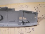
An overall inspection and test-fitting of the parts, will also indicate where any corrections or modifications may be needed, and allow the planning and measurement for any intended scratch-built areas, such as extra interior detail.
So, on with the first stage of the build process, with the photos below explaining what's what.
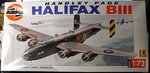
PIC 1. The Airfix kit in one of its later issues, obtained from a specialist dealer I use quite often, at 'normal' prices.
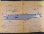
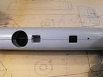
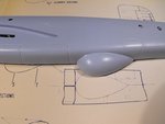
PIC 2. Using scale plans I've had for over 30 years, the fuselage halves were checked for general dimensional accuracy and location of hatches, turrets etc. This exercise indicated that the fuselage (not including nose transparency and rear turret) is 2mm short at the tip of the nose, and 2.5mm short at the tail turret platform, equivalent to a combined overall length discrepancy of approximately 1 foot. To be honest, this doesn't concern me too much, as the overall 'look' is fine, and this will not be noticed once the model is built and painted. What is possibly more important, is the location of the mid-upper turret which, in the kit, is slightly too far forward. With some surgery, this could be corrected, but again, in the overall appearance, it's hardly noticeable, so I'll accept it as it is.
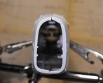
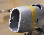
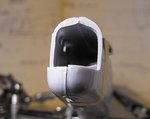
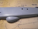
PICS 3 and 4. Something which would be noticeable is the shape and thickness of the opening at the bomb aimer's position, so this will be filed down, thinned and re-profiled to give a more scale appearance on the finished model.
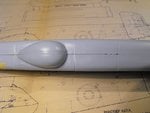
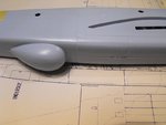
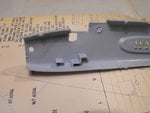
PIC 5. Test fitting pays dividends - ten fold! A first test fit shows that the extreme tail area is mis-aligned, and investigation showed that this is due to the locating pins and holes being slightly 'out', no doubt due to the age of the moulds. This was simply rectified by enlarging the locating hole, and filing down the pin, to allow some vertical movement when the time comes to join the fuselage halves. The rather 'heavy' turret fairing will also be thinned later.
Rather than make a long, complex initial post, I'll split this introduction, and continue in post Number 2, immediately following this.
Background.
This is being built for Mike Harrison, who's Uncle, along with the entire crew of the Halifax, was killed on 25th April 1944, after returning from a raid on Karlsruhe, Germany.
The Halifax, from 'B' Flight, 76 Squadron, was on approach to it's base at Holme on Spalding Moor (Spaldington), Yorkshire, when it was shot down and destroyed by a Me410 intruder. The crew, all from the RAFVR (RAF Volunteer Reserve), were returning from their 17th Operation, having started their Tour with the Squadron on October 22nd, 1943, with a trip to Kassel.
Halifax LK789 was built at the Fairey Engineering factory at Stockport, Cheshire, a few miles south of Manchester, in early 1944, being delivered to 76 Sqn on February 22nd. Coincidentally, the last time I built a model of a Halifax was in the early 1980s, at which time I was living quite close to the Fairey factory which, at that time, was still an engineering company, although no longer building complete aircraft. One of my neighbours had worked at the factory, and another had been a Halifax pilot!
This Halifax had completed 11 operations when it set out for Karlsruhe, and was completing its 12th, when shot down. Of the 17 Operations completed by the crew, the last nine were undertaken in this aircraft, 'L - Love'.
The Model.
The aim of this build is to provide a Memorial to Mike's Uncle and crew, and to all of the more than 55,000 members of Bomber Command who lost their lives during the course of World War Two, so that we can enjoy the freedom and peace they fought for.
The intention here is to build a diorama depicting the Halifax being 'bombed up' at its dispersal at Holme, in preparation for its 12th, and final, mission.
There is a secondary aim also, which is to (hopefully) help those who are newcomers to the modelling hobby, by explaining and illustrating how to go about building a rather basic kit, compared to today's 'shake and bake' offerings, in terms of planning, what to look out for, and how to correct errors or problem areas, as well as introducing some simple scratch-building techniques which can go some way to improve an otherwise 'empty' model.
To this end, and because it's the only game in town, I will be using the venerable Airfix kit, which was first released in the early 1960s, and has been re-released on numerous occasions, although currently out of general circulation. At the time of first release, the kit was considered 'state of the art', with what was then finely detailed parts, and rivet details etc. Of course, by today's standards, this is now seen as bordering on crude, but the basics are there, and a reasonable model can be produced out of the box, and with a little work, not unexpected on such an old kit, a very nice model can result - I hope!
The problem areas, and the solutions to these, will be explained and illustrated wherever possible, as the build progresses, but, as with any build, the first stage (after the research) is the planning, and in this case, that includes the diorama setting, and what is needed on the model to fit the scene to be portrayed.
A diorama is a picture in 3D, and all elements of this picture should work together to produce the desired image - the picture would look wrong if the main subject (in this case the aircraft) was just dumped haphazard into the middle of an unrelated scene. This means that the base has to be planned around the aircraft model, and the model has to be built to fit with the 'action elements' in the scene being depicted. Each and every item has to have a reason for being there, and each section element has to be 'doing something' to complete the picture, rather than just being there for the sake of it.
Even in the relatively small scale of 1/72nd, a heavy bomber dispersal and its associated equipment and personnel, takes up a lot of space, therefore some compromises have to be made, without detriment to the 'picture', in order to produce a finished product of manageable proportions.
This is where the planning pays dividends, by allowing the builder to construct the scene comfortably, and building the aircraft model to the requirements of the desired scene.
The Build.
As the model will be shown being 'bombed up', this will entail some surgery, as the kit is moulded with the bomb bays, and all hatches, in the closed position. So, before attacking plastic with knife or saw, it is necessary to check that those areas which need to be removed, can be removed, without affecting the rest of the construction, whilst maintaining the structural integrity of the model. Checking this will also help in identifying if the mouldings are accurate, or not, as the case may be - it would be a bit embarrassing to find that one has cut away the wrong piece!
An overall inspection and test-fitting of the parts, will also indicate where any corrections or modifications may be needed, and allow the planning and measurement for any intended scratch-built areas, such as extra interior detail.
So, on with the first stage of the build process, with the photos below explaining what's what.
PIC 1. The Airfix kit in one of its later issues, obtained from a specialist dealer I use quite often, at 'normal' prices.
PIC 2. Using scale plans I've had for over 30 years, the fuselage halves were checked for general dimensional accuracy and location of hatches, turrets etc. This exercise indicated that the fuselage (not including nose transparency and rear turret) is 2mm short at the tip of the nose, and 2.5mm short at the tail turret platform, equivalent to a combined overall length discrepancy of approximately 1 foot. To be honest, this doesn't concern me too much, as the overall 'look' is fine, and this will not be noticed once the model is built and painted. What is possibly more important, is the location of the mid-upper turret which, in the kit, is slightly too far forward. With some surgery, this could be corrected, but again, in the overall appearance, it's hardly noticeable, so I'll accept it as it is.
PICS 3 and 4. Something which would be noticeable is the shape and thickness of the opening at the bomb aimer's position, so this will be filed down, thinned and re-profiled to give a more scale appearance on the finished model.
PIC 5. Test fitting pays dividends - ten fold! A first test fit shows that the extreme tail area is mis-aligned, and investigation showed that this is due to the locating pins and holes being slightly 'out', no doubt due to the age of the moulds. This was simply rectified by enlarging the locating hole, and filing down the pin, to allow some vertical movement when the time comes to join the fuselage halves. The rather 'heavy' turret fairing will also be thinned later.
Rather than make a long, complex initial post, I'll split this introduction, and continue in post Number 2, immediately following this.
")