H.P. Halifax B.MkIII Dedication.

Ad: This forum contains affiliate links to products on Amazon and eBay. More information in Terms and rules
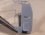
where do you get 1/72nd scale plans,i've been looking for some for years,the old aviation news i used to get as a kid had them but in the moves over the years i've lost all the plans i'd saved
 
Bob, most of my scale plans are nearly all 30+ years old, and from Aviation News or Model and Allied Publications plans service, both since faded away.
 
Very detailed tutorial Terry. I take my hat off to you for the time and expertise you put into this forum. I'm sure it'll turn out as brilliant as always.

Cheers,

Gerry
 
Oh my oh my. Terry that is an incredible amount of work and thanks for all the scribing, many useful hints there. Maybe there is even a book in it!!
 
Thanks very much Gerry and Vic. If the model turns out well, and a few people learn something from the efforts, then I'll be happy. I had actually considered writing a basic 'How to' booklet, for 'publication' on the forum, and might get around to doing so one day.
 
And thank you Wayne !
Just had an e-mail from Mike, who has looked at this thread to date. Happy to say he's more than pleased with the work so far (phew, relief!). He's also sent me the Bomb Aimer's 'Bomb Log' pages for MP-L, covering the three or four 'ops' prior to the last flight. This shows what the bomb loads were made up from, for example 1,000 and 500 pound HE bombs, 2,000 pound HE and incendiary cannisters of two types of incendiary and so on. (note that the Halifax could not accommodate the 4,000 pound 'cookie' in the fuselage bomb bay - the aircraft was designed to the original AM Spec requirement, which, when drafted, was based with the biggest bomb then available being 2,000 pounds. The design of the main bomb bay could accept this bomb, and 500 and 1,000 pounders, and of course there were the extra wing root bomb bays. However, unlike the Lancaster, which also had a deeper bomb bay, the Halifax had 'split' bomb bay doors on each side, so could not have 'bulged' doors fitted to cover the 4,000 pound bomb.)
The 'bomb log' has some interesting info - an industrial target attacked a few nights before the last operation was a rail marshalling yard, where the load was entirely HE, made up of 1,000 and 500 pound bombs. The raid two nights before the fatal last 'op' was to Dusseldorf, and the load was 1 x 2,000 pound HE bomb, with the remainder being a mix of the large incendiary, and the smaller, 4 pound incendiary, carried in the standard containers, in both wing root bays and the main, fuselage bay. Based on this, with the final target on the night the aircraft was lost being Karlsruhe, I'm going to surmise that it was classed as 'Industrial', and have the bomb load depicting HE bombs, which will be shown on trolleys, and being loaded into the bays.
I still have some studying to do regarding the topography and immediate geography around the area of 'B' Flight's dispersal points, so that I can model the dispersal pan as accurately and authentically as possible, within reason. Once I've done this, I'll be producing a sketch plan for Mike, to show the layout of the diorama, and I'll post a copy here too.
Meanwhile, I'm off to get a couple of hours snooze, to try to get my sleep pattern back in sync, then it's back to work on the construction of the bomb bay, and the start of some interior detailing.
Thanks again for your extremely complimentary comments, and continued interest, and I'll try to post some pics later tonight.
 
Sorry chaps, no further progress pics at the moment. Whilst doing a little more incidental research, I spotted a couple of small details in photos of 76 Squadron's MkIIIs which I need to check out before proceeding, as the deletion or addition of these, if required, will have a bearing on the construction sequence, particularly the interior detail scratch-building.
So, rather than leave you all 'empty handed', here are a couple of photos showing the airfield site at Holme on Spalding Moor.
PIC 1. This oblique photo was taken in June 1945, and shows the airfield in the centre, looking north. The light-coloured line running west to east (L to R) in the picture, inside the airfield boundary, is the southern perimeter track, bordering the road known as Drain Lane, and this is where the 'B' Flight dispersals were located, ten of them, each side of the peri track, to the 'frying pan' pattern. One of these was occupied by MP-L, and it is this area which will be depicted in the diorama.
PIC 2. A satellite shot from 2007 shows the airfield returned to agriculture, with only part of the main 'Tech Site' remaining (top of picture). The dog-legged road running left to right is Drain Lane, and from this vertical shot, it can be seen that the outer dispersal pans were bordering the very edge of this road, separated from the airfield only by hedges and a wire fence.
And a correction from my opening post - there was one survivor from the crash of the Halifax. This was the rear gunner, F/Sgt John Anderson, who was trapped in his turret when the aircraft, on fire, hit the ground, apparently at a shallow angle. Freed by firemen and other rescuers, he was rushed to Ely hospital, suffering a broken femur and abrasions of the skull, where his injuries were taken care of.
I'll post a more detailed account of the interception and loss of the Halifax, including the ultimate fate of the Luftwaffe Me410 crew involved, in a later 'instalment', and I hope to have more progress pics very soon.
EDIT:- For some strange reason, the pics will not appear in the order selected in 'Manage Attachments', but I'm sure you'll figure it out!
 

Attachments

  • HoSM June 45.jpg
    HoSM June 45.jpg
    77.6 KB · Views: 79
  • holme2007.jpg
    holme2007.jpg
    55.9 KB · Views: 94
Last edited:
Interesting Terry. Google Earth is quite interesting to tour for old bomber bases. The remnants of runways and building are, in many cases, still quite evident.

BTW, just came across this while browsing: BBC - WW2 People's War - Beating the Odds. Another story of a Halifax crew on the same mission and Mike's uncle plus a picture.
 
Last edited:
Thanks chaps, an d thanks for that link Andy. The photo shown in it also confirms some of the details I've been checking out.
 
Good stuff Andy.It's always a bit sad to see such places fade away. Last time I drove past HoSM was in the 80s, when it was still being used by BAe, so a lot of changes since then. And to think, to those not 'in the know', passing such places, they would never know that the open fields with the odd dilapidated building here and there, were once the 'home' to a couple of thousand souls, for some of whom it would be the last place they ever saw.
As air warfare didn't have, or doesn't have, a defined, tangible 'battlefield', I always think of the airfield sites as this field, the main connection between the campaigns, and the men and machines involved.
 
And back to the model, with some actual construction taking place at last.
The modifications to the kit parts in order to construct the bomb bay have been done, the bomb bay components fabricated, assembled and fitted, and work has commenced on some interior detail, restricting this to those areas where there is a slight chance of it been seen, mainly the nose and cockpit area.
PICS 1 and 2. Show the forward fuselage components loosely assembled and test fitted, to check on clearance for the bomb bay bulkheads and roof. Note how the bottom of the rear bulkhead (flight engineer's panels) protrudes into the area of the bomb bay. This has been modified accordingly. The pencil lines are an approximate guide to where frames and stringers will be added to the fuselage walls.
PIC 3. The area of bulkhead to be removed has been cross-hatched in pencil.
PIC 4. The piece was then carefully removed, using a razor saw, cleaned up and retained, as it will now form the forward bulkhead of the bomb bay.
PIC 5. The locating rib for the bulkhead was also cut back, to prevent it fouling the bomb bay roof, when fitted.
PIC 6. The bomb bay roof, and forward and rear bulkheads, were cut from plastic card (the forward b'head being the part retained earlier), and varying widths of plastic strip were added to represent the beams, and the reinforcing ribs respectively.
PIC 7. The components were then cemented into place, with small strips of plastic acting as locating ribs for the bulkheads, whilst the moulded ribs for the forward floor provided a 'notch' against which the front end of the bomb bay roof could sit.
PIC 8. The bomb bay is slightly shallower than it should be, as the wing locating slots would interfere if the roof was raised further. However, this is not a major concern as, once the doors are hung in the open position, and the model is fixed to the display base, this should not be noticeable.
PICS 9 and 10. With the bomb bay assembly now set, the fuselage halves were test-fitted to check clearance and fit, and thankfully, it all fits as intended.
PIC 11. The first stage of adding some detail began with the bulkhead which forms the rear of the Pilot's cockpit, with the Wireless Operator's 'cabin' below it. This should have armoured glass windows at the top, and the W/Op's seat needs some side panels, not that much will be seen of the latter - but ... well, you know how it goes!
PIC12. Holes were drilled across the area where the 'windows' need to be, then cuts made between the holes to remove the bulk of the unwanted plastic. The aperture was then filed to shape, using a half-round jeweller's file.
PIC 13. The diagonal window frames were added from thin plastic strip, and the seat sides from thin plastic card. The latter have yet to be filed to shape, the bulkhead cleaned-up and the remains of the ejector pin marks sanded off.
Next step is to add the internal frame work, then detail and paint the main instrument panel, and the Flight Engineer's panels, before moving on to some detail work in the Navigator's and Bomb Aimer's areas.
Thanks again for your interest, and I hope to post another up-date tomorrow.
 

Attachments

  • Halifax build 077.jpg
    Halifax build 077.jpg
    57.6 KB · Views: 84
  • Halifax build 078.jpg
    Halifax build 078.jpg
    49 KB · Views: 86
  • Halifax build 082.jpg
    Halifax build 082.jpg
    53.1 KB · Views: 79
  • Halifax build 084.jpg
    Halifax build 084.jpg
    44.6 KB · Views: 82
  • Halifax build 083.jpg
    Halifax build 083.jpg
    38.8 KB · Views: 91
  • Halifax build 085.jpg
    Halifax build 085.jpg
    53.1 KB · Views: 77
  • Halifax build 086.jpg
    Halifax build 086.jpg
    63.7 KB · Views: 76
  • Halifax build 087.jpg
    Halifax build 087.jpg
    59 KB · Views: 86
  • Halifax build 091.jpg
    Halifax build 091.jpg
    62.9 KB · Views: 78
  • Halifax build 092.jpg
    Halifax build 092.jpg
    67.2 KB · Views: 78
  • Halifax build 095.jpg
    Halifax build 095.jpg
    67.9 KB · Views: 85
  • Halifax build 098.jpg
    Halifax build 098.jpg
    85.4 KB · Views: 88
  • Halifax build 103.jpg
    Halifax build 103.jpg
    49.6 KB · Views: 83

Users who are viewing this thread

Back