Lucky13
Forum Mascot
A pint to your health Sire!
Follow along with the video below to see how to install our site as a web app on your home screen.
Note: This feature may not be available in some browsers.
Ad: This forum contains affiliate links to products on Amazon and eBay. More information in Terms and rules

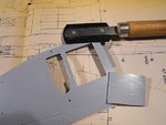
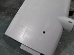
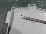
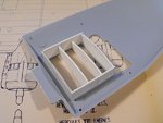
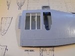
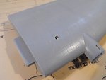
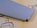
Thanks my friend. As far as I've been able to ascertain, the dividing walls had vertical frames on each side, along their length. When I add the bottom frames to each cell wall, I'll also fit some vertical frames, but keep it simple, as not much will be seen. All of the wing bays except one, maybe two, on the port side will have bombs in place, and the model will be fixed to the diorama base, so not much will be visible under the shadow of the wings.