Navigation
Install the app
How to install the app on iOS
Follow along with the video below to see how to install our site as a web app on your home screen.
Note: This feature may not be available in some browsers.
More options
You are using an out of date browser. It may not display this or other websites correctly.
You should upgrade or use an alternative browser.
You should upgrade or use an alternative browser.
H.P. Halifax B.MkIII Dedication.
- Thread starter Airframes
- Start date
Ad: This forum contains affiliate links to products on Amazon and eBay. More information in Terms and rules
More options
Who Replied?- Thread starter
- #162
Airframes
Benevolens Magister
Thanks my friend!
fubar57
General
Excellent work as always Terry. 60 hours!!!! Ye gads...most of mine are measured in months.
Geo
Geo
- Thread starter
- #164
Airframes
Benevolens Magister
Thanks George.
Aaron Brooks Wolters
Brigadier General
Looking forward to more sir.
Nicely done so far Terry!
- Thread starter
- #167
Airframes
Benevolens Magister
Thanks Aaron and Hugh.
Got a little more done tonight, and decided to see how the vac-formed canopy will work out, before moving on to work on the engines.
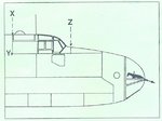
PIC 1. This is the diagram from the 'Squadron' vac-form canopy set, which shows where the kit fuselage needs to be cut in order to obtain the correct fit. Had I been aware of this, and obtained the canopy before commencing work on the kit, I would have been able to make these cuts without problem, but it would be extremely tricky, and could possibly lead to damage of the internal parts, if attempted at this stage. Therefore, after checking potential problem areas around the cockpit of the model, I decided to cut the canopy from the moulding around the lines of the edge framing, and then trim or fill areas on the fuselage as required.
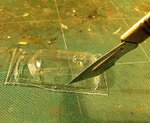
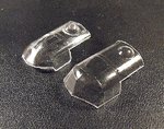
PIC 2. The canopy was first carefully cut away from the rest of the mouldings then, with a new blade in the scalpel, it was removed from the surrounding material. To do this, do not attempt to make immediate cuts, as there is a very real risk of ruining the canopy by splitting the acetate, or slipping and cutting through the wrong area. Instead, very carefully score along the cut lines repeatedly, following one axis at a time, until the blade cuts through the material. Repeat this for each section, until the part comes free from the sheet. This will ensure that the part is removed cleanly, and with only a little sanding required in order to clean up the cut edges. Do not be tempted to rush, be patient and take it steady, one section at a time, and be prepared for a relatively lengthy operation - this particular canopy took around one hour to cut out.
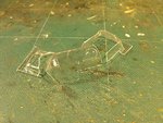
PIC 3. With the part now removed, it can be test-fitted before carefully and gently sanding the edges to eliminate any burrs or irregularities.
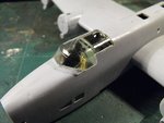
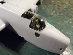
PICS 4 and 5. The canopy has been loosely placed in position over the cockpit to check overall fit. This shows that a little trimming of the fuselage will be required at the front of the cockpit on the port side, whilst on the starboard side, a gap will need to be filled at the rear of the cockpit section.
The trimming can be done with the aid of a razor saw, then carefully sanded, but the gap will involve slightly more work.
The fuselage wall will first be sanded slightly to straighten the line, then a piece of plastic card will be cemented in place and, when fully set, filled and sanded at the joint as necessary, and the interior face of the 'plug' painted in the cockpit colour. The canopy will be test-fitted regularly during this process, to ensure the trimming and plastic 'plug' are properly aligned with the canopy edges to provide the best possible fit. When satisfied that the canopy will fit, and can be attached securely, the modified area will be polished and then primed to cover the joints.
As the canopy itself is thin, and will probably be secured mainly with Micro 'Kristal Klear' to avoid the possibility of fogging if CA glue is used, it will be fitted after painting the model, the joints sealed with 'Kristal Klear' and then re-touched with the appropriate colour. This will eliminate the risk of the canopy becoming detached when removing the masks after painting. The canopy frames will be done by adding pre-painted strips of tape, before fitting it to the model, as paint itself, if applied directly to the transparent plastic, tends not to cover or adhere very well on such small, narrow areas.
PIC 6. Comparison with the original kit canopy (top) and the vac-formed item show that this extra work should be well worth the effort and, given that the new canopy fits well, should make a tremendous difference to the overall appearance of the finished model.
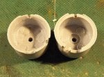
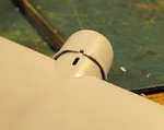
PIC 7. Moving on to the engines, the first requirement is to improve the eventual appearance of the gills on the rear of each cowling.
On the right is a standard kit part, with a modified item on the left. The inner faces have been pared down and then filed in order to thin them out, and the fine, raised lines of each cowl flap have been sanded off, although these aren't visible in this photo. The lines for each flap will be engraved and, where required, partly sawn through with a fine-bladed razor saw, to present a more realistic appearance.
PIC 8. An example of the unmodified kit part.
PIC 9. And how the same area looks after modification.
That's all for now, but I hope to post another up-date sometime tomorrow. I hope the description of the treatment of the vac-formed canopy has proved useful to some, and that the rest is interesting to others, and thanks once again for your kind comments.
I'd particularly like to thank Mike Harrison for the information he has recently supplied concerning his Uncle's final operation, a summary of which I will post here soon, and for help in confirming the fitting of certain equipment in 76 Squadron's aircraft during the period in question, notably the fitting and use of the 'Monica' tail-warning radar, and the bomb load for the raid on Karlsruhe in April 1944.
Got a little more done tonight, and decided to see how the vac-formed canopy will work out, before moving on to work on the engines.
PIC 1. This is the diagram from the 'Squadron' vac-form canopy set, which shows where the kit fuselage needs to be cut in order to obtain the correct fit. Had I been aware of this, and obtained the canopy before commencing work on the kit, I would have been able to make these cuts without problem, but it would be extremely tricky, and could possibly lead to damage of the internal parts, if attempted at this stage. Therefore, after checking potential problem areas around the cockpit of the model, I decided to cut the canopy from the moulding around the lines of the edge framing, and then trim or fill areas on the fuselage as required.
PIC 2. The canopy was first carefully cut away from the rest of the mouldings then, with a new blade in the scalpel, it was removed from the surrounding material. To do this, do not attempt to make immediate cuts, as there is a very real risk of ruining the canopy by splitting the acetate, or slipping and cutting through the wrong area. Instead, very carefully score along the cut lines repeatedly, following one axis at a time, until the blade cuts through the material. Repeat this for each section, until the part comes free from the sheet. This will ensure that the part is removed cleanly, and with only a little sanding required in order to clean up the cut edges. Do not be tempted to rush, be patient and take it steady, one section at a time, and be prepared for a relatively lengthy operation - this particular canopy took around one hour to cut out.
PIC 3. With the part now removed, it can be test-fitted before carefully and gently sanding the edges to eliminate any burrs or irregularities.
PICS 4 and 5. The canopy has been loosely placed in position over the cockpit to check overall fit. This shows that a little trimming of the fuselage will be required at the front of the cockpit on the port side, whilst on the starboard side, a gap will need to be filled at the rear of the cockpit section.
The trimming can be done with the aid of a razor saw, then carefully sanded, but the gap will involve slightly more work.
The fuselage wall will first be sanded slightly to straighten the line, then a piece of plastic card will be cemented in place and, when fully set, filled and sanded at the joint as necessary, and the interior face of the 'plug' painted in the cockpit colour. The canopy will be test-fitted regularly during this process, to ensure the trimming and plastic 'plug' are properly aligned with the canopy edges to provide the best possible fit. When satisfied that the canopy will fit, and can be attached securely, the modified area will be polished and then primed to cover the joints.
As the canopy itself is thin, and will probably be secured mainly with Micro 'Kristal Klear' to avoid the possibility of fogging if CA glue is used, it will be fitted after painting the model, the joints sealed with 'Kristal Klear' and then re-touched with the appropriate colour. This will eliminate the risk of the canopy becoming detached when removing the masks after painting. The canopy frames will be done by adding pre-painted strips of tape, before fitting it to the model, as paint itself, if applied directly to the transparent plastic, tends not to cover or adhere very well on such small, narrow areas.
PIC 6. Comparison with the original kit canopy (top) and the vac-formed item show that this extra work should be well worth the effort and, given that the new canopy fits well, should make a tremendous difference to the overall appearance of the finished model.
PIC 7. Moving on to the engines, the first requirement is to improve the eventual appearance of the gills on the rear of each cowling.
On the right is a standard kit part, with a modified item on the left. The inner faces have been pared down and then filed in order to thin them out, and the fine, raised lines of each cowl flap have been sanded off, although these aren't visible in this photo. The lines for each flap will be engraved and, where required, partly sawn through with a fine-bladed razor saw, to present a more realistic appearance.
PIC 8. An example of the unmodified kit part.
PIC 9. And how the same area looks after modification.
That's all for now, but I hope to post another up-date sometime tomorrow. I hope the description of the treatment of the vac-formed canopy has proved useful to some, and that the rest is interesting to others, and thanks once again for your kind comments.
I'd particularly like to thank Mike Harrison for the information he has recently supplied concerning his Uncle's final operation, a summary of which I will post here soon, and for help in confirming the fitting of certain equipment in 76 Squadron's aircraft during the period in question, notably the fitting and use of the 'Monica' tail-warning radar, and the bomb load for the raid on Karlsruhe in April 1944.
Attachments
-
 Halifax build.jpg28.9 KB · Views: 109
 -
 Halifax build 213.jpg101.1 KB · Views: 106
 -
 Halifax build 221.jpg83 KB · Views: 97
 -
 Halifax build 217.jpg46.4 KB · Views: 85
 -
 Halifax build 219.jpg51.4 KB · Views: 111
 -
 Halifax build 223.jpg139.2 KB · Views: 98
 -
 Halifax build 225.jpg89.3 KB · Views: 103
 -
 Halifax build 227.jpg72.4 KB · Views: 91
 -
 Halifax build 226.jpg59 KB · Views: 101
Crimea_River
Marshal
Great stuff Terry.
A4K
Brigadier General
With Andy...good stuff Terry!
Would only add re the vac form canopies that it is best to trim them holding the blade at a 45 degree angle to the cut. The blade is more easily guided along the line to be cut and lowers the risk of slipping.
Also that the Squadron range of canopies are seperately sold versions of the Falcon canopy set range, the Halifax replacement canopies for the Airfix and Matchbox/ Revell kits from set 17: 'RAF, World war II, part 2'.
Tony Hill
Tech Sergeant
Just caught up with the whole thread...great stuff Terry!!!
Lucky13
Forum Mascot
Smashing work old boy!
- Thread starter
- #172
Airframes
Benevolens Magister
Thanks very much chaps. You're correct Evan about the Falcon sets. BTW, the blade was used at 45 degrees or thereabouts - for the photo it's being supported by the 'Helping Hands' desk clamp.
A4K
Brigadier General
Good man Terry, just mentioned it for the purposes of the tutorial.
Matt308
Glock Perfection
Nice stuff! I'm enjoying this one.
- Thread starter
- #175
Airframes
Benevolens Magister
Thanks Matt, and no problem Evan.
I might have a little more to show later tonight.
I might have a little more to show later tonight.
- Thread starter
- #176
Airframes
Benevolens Magister
Nothing much of interest to show at the moment, still working on the engines. But a short up-date about the information flowing in.
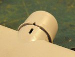
One of our members, Sander (Kingscoy), in Holland, has replied in another thread with some possible information about the Small Bomb Containers. Not only does he have the remains of one in the store his recovery group use to house artefacts recovered from WW2 crash sites in the Netherlands, but he has posted a general shot of this. He is also going to check the dimensions for me on Friday, and if possible, get a photo of the attachment brackets for the bomb carrier - fantastic!
Thanks again Sander.
This forum never ceases to amaze me.
The diorama project was started by a suggestion/request from a member in Canada (Andy), and taken up by a guy from County Durham, living in Cheshire, UK (me), to be built for Mike, living in Nottingham, UK, the relative of a crew member who took off from Spaldington, Yorkshire, UK, flew to Karlsruhe, Germany, and was shot down near Cambridge, UK.
Help with decals has been offered by a New Zealander living in Hungary (Evan), and the kit being used was designed in England, manufactured in France, and will have spare parts incorporated made in Germany and the UK, with accessories made in Germany, UK, Poland, Italy, the USA via New Zealand, and the Czech Republic, and other materials from China, Korea, Burma and the USA.
Information has been received from a contact of Mike's in Canada, with reference photographs from Yorkshire (UK) and Canada, printed work from the National Archives in Kew (UK), and a 'strike' photo taken over the target at Karlsruhe, Germany, and further information about to be received from Holland.
Other reference material has originated in UK, Germany, Canada and the USA, with some images being from a satellite of unknown nationality, the 'hand over' of the finished diorama will take place at a former RAF station at Newark, UK, and I'm now wondering where the next little gem will pop up from!
Stewth! This really is an international forum of cooperation !
A4K
Brigadier General
If that dosen't sum up this forum in one mouthful (if not breath!) then I don't know what does! Gotta love this place... ")
Keep up the good work Terry, gonna be another beauty when done...
Keep up the good work Terry, gonna be another beauty when done...
Matt308
Glock Perfection
Thankyou, Terry. That was very nice of you to take the time to point out the international comraderie of this forum. Good on you. I'll speak for all the Mods on this one and say that we all appreciate the participation from everyone, irrespective of country of origin.
...well except maybe Canada.
Just kidding!!!!
...well except maybe Canada.
Just kidding!!!!
Lucky13
Forum Mascot
Canada? Think that I might have heard about that place.... 
True! It IS some place this!
True! It IS some place this!
- Thread starter
- #180
Airframes
Benevolens Magister
It sure is - especially with a person using Glaswegian phrases spoken in a Swedish accent !
Users who are viewing this thread
Total: 1 (members: 0, guests: 1)