wonderfull Terry
Navigation
Install the app
How to install the app on iOS
Follow along with the video below to see how to install our site as a web app on your home screen.
Note: This feature may not be available in some browsers.
More options
You are using an out of date browser. It may not display this or other websites correctly.
You should upgrade or use an alternative browser.
You should upgrade or use an alternative browser.
H.P. Halifax B.MkIII Dedication.
- Thread starter Airframes
- Start date
Ad: This forum contains affiliate links to products on Amazon and eBay. More information in Terms and rules
More options
Who Replied?Crimea_River
Marshal
Glad Mike is pleased Terry - he should be.
Fantastic job Terry!
- Thread starter
- #304
Airframes
Benevolens Magister
Thanks very much indeed chaps.
Yes, Mike would like the model depicting preparations for the final 'Op'. I've therefore removed the 'bomb log', and replaced it with the correct number of Operations flown (11). The remainder of the decals are now in place, including the 'decal' serial numbers, which have worked out quite well - even though it goes against the grain to have a decal visible!
I've had a few interuptions today, so I'm just about to spray the matt clear coat now. I'll try to post some pics later.
A4K
Brigadier General
Looking forward Terry!
- Thread starter
- #306
Airframes
Benevolens Magister
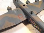
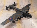
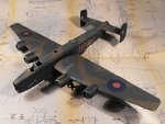
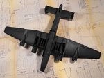
And here they are. A few shots of some of the smaller decals, and how the model looks oversll so far, with all decals in place, and the matt clear coat applied.
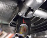
PIC 1. The aircraft's individual code letter was carried on the front of each main undercarriage leg, so these were replicated by using 1/48th scale RAF serial number letters. The model has not had the matt clear coat applied in this shot, and the undercart leg has yet to have a semi-matt clear coat, and the small details are yet to be painted.
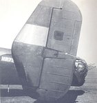
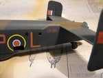
PICS 2 and 3. As previously mentioned, the real Halifax had its serial number applied as a decal, which was noticeable close up, or at longer distances in certain lighting conditions. Here is an example, together with my version which, although not perfect, works quite well, and looks better to the naked eye. This was printed as red letters on a black background, onto white decal paper. The density from an ink jet printer, although it appears to the human eye to be heavy, is actually not that good on larger areas of solid colour, and this is magnified when using decal paper. It was this fact which prompted me to print onto white paper, rather than clear, knowing it would give a different tone compared to the painted background. I could have possibly achieved a similar result using clear decal paper, but the red characters would have appeared to be more towards a pink shade when applied, again due to the lack of ink density.
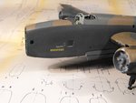
PIC 4. The correct number of bomb symbols have now been added, using an adapted decal from a spare sheet, which is at least 35 years old!
PIC 5. The dinghy hatch outline markings were painted on, but still require a little re-touching and the hatch itself needs a little work around the panel lines. The beginnings of some light exhaust staining and paint wear are also visible in this shot, and some further light weathering and panel line outlines will be added later.
PICS 6 to 8. How the model looks to date.
Next step is to complete the detail painting, including the exhaust collector rings, then add the detail parts such as wheels and exhausts. I hope to get a lot more done in the next couple of days, and will post another up-date when there's something to show.
Thanks again for your kind comments and continued interest.
Attachments
-
 Halifax build 278.jpg68.1 KB · Views: 83
 -
 Halifax build 274.jpg36.6 KB · Views: 81
 -
 Halifax build 283.jpg78.5 KB · Views: 77
 -
 Halifax build 282.jpg76 KB · Views: 97
 -
 Halifax build 285.jpg80.1 KB · Views: 83
 -
 Halifax build 280.jpg104.1 KB · Views: 89
 -
 Halifax build 281.jpg101.8 KB · Views: 83
 -
 Halifax build 284.jpg104.5 KB · Views: 103
Crimea_River
Marshal
Looks the biz Terry!
You had mentioned earlier you were going to write a bit about the circumstances surrounding this shoot down based on Mike`s research or am I wrong.
You had mentioned earlier you were going to write a bit about the circumstances surrounding this shoot down based on Mike`s research or am I wrong.
- Thread starter
- #308
Airframes
Benevolens Magister
Thanks Andy, and yes, I will be posting the background to the loss of LK789. I wanted to get the model to an advanced stage first, but I'll probably post the info over the weekend. Fortunately, unless I hit any more major glitches, I'm now back on track, and should have the diorama completed in time for hand over on September 7th.
Leaves me about 13 days in which to get the model finished, the base made and 'dressed' and all the elements of the diorama in place, before packing it for transit.
Methinks I'll be burning a tanker full of midnight oil ...!
Leaves me about 13 days in which to get the model finished, the base made and 'dressed' and all the elements of the diorama in place, before packing it for transit.
Methinks I'll be burning a tanker full of midnight oil ...!
A4K
Brigadier General
Terry - just beautiful. Mike will be stoked!!!
looking better with every update Dogsbody
T Bolt
Colonel
Very nice Terry, Mike should be pleased.
- Thread starter
- #313
Airframes
Benevolens Magister
Thanks very much indeed chaps. I've got a few small details done, including glazing the small round windows and lower bomb-aimers window, but no photos yet.
I'll post a brief account of the background to the model, in PDF format, later tonight.
I'll post a brief account of the background to the model, in PDF format, later tonight.
Looks great so far Terry!
- Thread starter
- #315
Airframes
Benevolens Magister
Thanks Hugh. Nothing worth showing yet - still working on bits and pieces, but should have some progress to show sometime over the weekend.
Meanwhile, as promised, here's the background to the story behind the model. It's in PDF format for ease of reading.
Meanwhile, as promised, here's the background to the story behind the model. It's in PDF format for ease of reading.
Attachments
Last edited:
Well done Terry, good addition to a great build!
- Thread starter
- #317
Airframes
Benevolens Magister
Thanks Wayne - the article has got Mike's approval too.
A little bit more to show, including my biggest concern of the whole build, fitting the vac-form canopy.
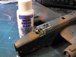
PIC 1. All the small 'port hole' windows have been glazed, using Micro 'Kristal Klear'. It doesn't show very well in this shot, due to the angle, but the windows are clear, and the interior can be viewed through them. For those who haven't used this material, which is basically refined PVA, it's quite simple to do, and the instructions state that apertures up to 1/4 of an inch (6 mm) can be glazed in this way, and I was able to successfully treat the bomb-aimers window on the underside of the nose without problems.
Using a cocktail stick, get a small 'blob' of the 'Kristal Klear' on the tip, and touch this to the edge of the aperture, then draw it out, moving the tip of the stick around until all the edges are in contact with the material, forming a membrane. It will be white and, if too much has been applied, it'll protrude from the aperture as a 'lump'. If this happens, pick some out with the stick, clean off the excess with a wet finger or cloth, and then stretch the remainder. As it dries, it will shrink back a little, and it will be perfectly clear when fully set. With practice, you'll get to know just how much to use to obtain a smooth, flush membrane, and be able to form virtually perfect windows, as well as domed or 'tear drop' lamps and similar clear items, by extruding the material. A word of warning though - don't try to coat it in clear acrylic varnish, as this will re-act, and make the material cloudy white again!
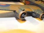
PIC 2. The exhaust collector rings have been painted, using a mix of brown, red, a touch of black, and silver, to give a metallic, burnt bronze finish. They will be given a coat of semi-matt clear acrylic varnish once the paint has fully cured. The 'porcupine' exhausts themselves will be fitted after adding some detail, in the way of breather and pressure pipes.
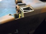
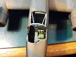
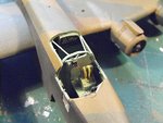
PICS 3 and 4. This is the part I've been concerned about - fitting the vac-form canopy - as, if I get it wrong, the entire model will be ruined!
The test fitting showed that the canopy will fit, after a fashion, but some packing of one area, and further trimming of other areas, would be required first. The rim of the port side of the engineer's compartment required a little packing, to at least partly close the gap between it and the bottom edge of the rear of the canopy, whilst the top of the bulkhead between cockpit and engineer's compartment needed to be filed down a touch, and the forward lip and starboard ledge of the cockpit itself needed thinning very slightly. The white strip of plastic is the packing, and the lighter areas around the bulkhead top and the cockpit edges are where the filing and trimming has been carried out. Also visible here are the two 'tubular' cross braces from the fuselage to the pilot's bulkhead, added from thin 'Evergreen' rod.
PIC 5. After clean-up, the bare areas were re-painted in the Cockpit Grey-Green, lightened with a touch of white for 'scale effect'.
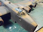
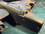
PICS 6 and 7. Fitting the canopy - Stage One. A thin bead of 'Kristal Klear' was applied around the edges of the opening, and across the top of the central bulkhead, and then the canopy was placed in position, and eased into place until it was aligned with the edges of the cockpit as best as possible. (This was rather awkward, due to the asymmetric shape of the cockpit opening - on a 'regular' shaped cockpit opening, positioning and fitting a vac-form part is relatively straight forward.) Once satisfied that the canopy was more or less in the desired position, it was gently pressed into place, and the glue allowed to almost fully set (about 30 or 40 minutes), before tackling the next stage.
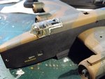
PICS 8 and 9. Fitting the canopy - Stage Two. The canopy was then very gently moved into its final position, relying on the now almost set glue to prevent it from slipping out of line, or springing back to its original position. Being thin and very flexible, vac-form parts have a tendency to want to 'spring' out of position at the slightest touch, exacerbated by static between fingers and plastic, causing it to 'stick' to one's finger. By allowing the first, thin bead of glue to partly set, this greatly reduces the amount of involuntary or unwanted movement when adjusting the part to the final position.
Once satisfied that the part is correctly positioned and aligned, another bead of 'Kristal Klear' is applied around the edges, and also 'teased' into any gaps. which will be filled by the material. There was a fairly large gap, measuring around 2 mm, at the base of the starboard side of the windscreen, where it meets the side sill, and this was successfully bridged, in a similar fashion to that used for making the windows, described above. Any excess glue is wiped off with a wet finger tip or, where access is difficult, by using the tip of a cocktail stick, also wet, and gently rubbing away the excess .
In these photos, the sealing and 'gap bridging' looks rather rough, but, when the KK dries, it will smooth out, shrink back slightly, and be clear. At this point, the canopy will be left for at least 6 hours, to ensure the bond is firm, and to allow the KK to fully harden. It will then be closely inspected under a magnifying glass, and any more gaps or depressions will be sealed with more KK and allowed to set.
Once the sealing is fully hardened ( I normally leave it at least 12 hours), then the area can be re-touched in the relevant colour, and given a coat of matt clear, and the canopy glazing polished with a cotton bud ('Q-Tip') to remove finger marks and grease left over from handling.
That's it for now, and I hope this will be of use to at least some of you.
Thanks again for your interest, and I should be able to post some more progress reports sometime over the weekend - it's a Public Holiday here in the UK this weekend and Monday, so plenty of time to shelter from the torrential rain and get some more modelling done!
Attachments
-
 Halifax build 303.jpg43 KB · Views: 84
 -
 Halifax build 300.jpg40.9 KB · Views: 72
 -
 Halifax build 286.jpg44 KB · Views: 82
 -
 Halifax build 287.jpg54.4 KB · Views: 78
 -
 Halifax build 289.jpg60.1 KB · Views: 88
 -
 Halifax build 295.jpg63.1 KB · Views: 92
 -
 Halifax build 292.jpg69.8 KB · Views: 89
 -
 Halifax build 305.jpg59 KB · Views: 78
 -
 Halifax build 306.jpg60.1 KB · Views: 82
- Thread starter
- #319
Airframes
Benevolens Magister
Thanks my friend. it should be OK, as there is no glue actually on the clear panels, only around the very edges, which were already painted. I shoud find out tomorrow though!
Users who are viewing this thread
Total: 1 (members: 0, guests: 1)
Similar threads
- Replies
- 31
- Views
- 8K
