**** DONE 1/48 Tamiya Me 262 A-2 Heavy Hitters Group Build

Ad: This forum contains affiliate links to products on Amazon and eBay. More information in Terms and rules

Having now put the wheels on, it was back to finishing the hydraulics and brake lines in the wheel wells.

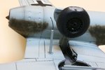
Photo 1 shows the completed nose wheel. The cylinder actuator has been attached to the strut and the hydraulic line run to the end of the cylinder. Not visible in this shot is the brake line that goes from the oleo along the wheel well behind the cylinder. The gear door and its actuator have been added.

Photo 2 shows the completed nose wheel and white nose with black border. Funny how the camera picks up defects the eye doesn't see. The paint splatter just behind the nose will be touched up - on the punch list.

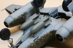
Next up was completing the main gear which started with running the brake line toward the fuselage, through the gusset and into the bowels of the fuselage (Photo 3). This had to be done before adding the gear actuating cylinders as they pretty much obliterated view of this area. Photo 4 shows the completed starboard gear with the cylinder in place and the two hydraulic lines for it run from the cylinder to join their brethren in the fuselage. Doors have been added and a little bit of wash to accentuate the panels is yet to be done.

Touch ups and fiddly bits remain. I just noticed a tear in one of the crosses on the underside of the wings. Solvaset has made it worse so I'll need to paint the offending spot.
 

Attachments

  • 091231 Nose Gear.jpg
    091231 Nose Gear.jpg
    95.4 KB · Views: 167
  • 091231 Nose Shot.jpg
    091231 Nose Shot.jpg
    88.7 KB · Views: 176
  • 100101 Brake Line.jpg
    100101 Brake Line.jpg
    88.2 KB · Views: 174
  • 100101 Main Gear Hydraulics.jpg
    100101 Main Gear Hydraulics.jpg
    89.7 KB · Views: 172
Here are a whole bunch of detail shots as I near completion of the jet.

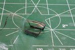
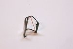
I decided rather late that I didn't like the barn door hinges that Tamiya supplied to fasten the open canopy so I decided to do away with these and do my own. The few pictures I saw of the open canopy reveal that it's a piano hinge type affair. So I cut off the offending slabs of plastic shown in Photo 1 and made some additional details on the canopy. Photo 2 shows the finished canopy with added details. On the port side, I added a little locking latch from card. The knob is a tiny piece of stretched sprue. The pointy pieces in the back were added from card but their purpose is a bit of a mystery. All I know is they show up in all photos of open canopies I've seen.

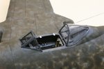
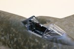
Photos 3 and 4 show the cockpit sides with the holes for the hinges filled in with card prior to filing and painting. Also seen in Photo 3 are the added gunsight and, to its immediate right, the small red emergency canopy eject lever I added with plastic card. Also seen in both shots is the entry point for the added radio antenna wire which enters through a small hole drilled in the rear canopy frame and help with CA glue.

Photo 5 shows the two complete 500kg bombs fitted to the racks. The rods on the back of the fins were added with wire inserted into small holes drilled in the fins.
Photo 6 shows the AAG-16 VHF antenna mast. The narrower tip was cut off from the kit-supplied piece and replaced with a bent piece of stretched sprue.
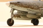
Photo 7 shows the port nose with the bombs attached, a wash of balck and brown applied to the inner gear door to simulate dirt and grease, and the offending paint splatter just behind the white nose seen in an earlier photo touched up.
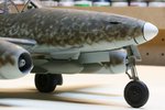
Photo 8 is a similar shot moving around to the starborad side.
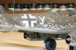
Photo 9 shows the starboard quarter. Seen below the cross is the AAG-25a rod antenna for the FuG-25a IFF transponder simply added with stretched sprue glued into a hole drilled in the fuselage.
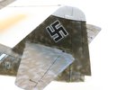
Photo 10 shows the attachment of the wire antenna to the fin. Just visible to the right on the elevator can be seen the stretched sprue actuator for the elevator trim tab. The port one is underneath. Also seen in this shot is the clear tail light at the bottom of the rudder. Tamiya provided a tiny hole in the molding so you could drop some paint into it to simulate the white bulb - a nifty touch.
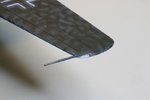
And finally, the last shot shows the pitot tube and port nav light. This was also provided with a little hole to drop a dab of red paint. White glue was added to blend in the lens with the wing as there were a few gaps. The RLM 75 touch ups along the wing leading edge need to be blended into the RLM 81 a bit more yet.

Sorry for the long winded post. Moving on to the Kettenkrad and figures now and thinking ahead to the base. Thanks for reading.
 

Attachments

  • 100103 Canopy Before Details 2.jpg
    100103 Canopy Before Details 2.jpg
    94.5 KB · Views: 194
  • 100103 Canopy Details.jpg
    100103 Canopy Details.jpg
    47 KB · Views: 191
  • 100103 Cockpit 2.jpg
    100103 Cockpit 2.jpg
    80.6 KB · Views: 200
  • 100103 Cockpit 1.jpg
    100103 Cockpit 1.jpg
    75.5 KB · Views: 206
  • 100103 Bombs.jpg
    100103 Bombs.jpg
    85.7 KB · Views: 186
  • 100103 AAG-16 Antenna Mast.jpg
    100103 AAG-16 Antenna Mast.jpg
    75.3 KB · Views: 197
  • 100103 Nose Port.jpg
    100103 Nose Port.jpg
    76.3 KB · Views: 192
  • 100103 Stbd Nose.jpg
    100103 Stbd Nose.jpg
    84.5 KB · Views: 239
  • 100103 Stbd rear.jpg
    100103 Stbd rear.jpg
    88.7 KB · Views: 204
  • 100103 Port Rudder 2.jpg
    100103 Port Rudder 2.jpg
    65.6 KB · Views: 192
  • 100103 Pitot.jpg
    100103 Pitot.jpg
    52.1 KB · Views: 199

Users who are viewing this thread

Back